
A key specification of a satellite receive system is the frequency stability. This is important for satellite systems engineers because it has an impact on carrier acquisition time, the size of the guard bands required between carriers, how many carriers can be squeezed onto a satellite and how much throughput the satellite can achieve. All of these affect the cost of your system and therefore the revenue potential.
Here are 5 things you need to know to manage Frequency Stability:
1: The phase locked loop controlled LNBs are better than simple LNBs
A PLL controlled LNB is a Low Noise Block Downconverter (LNB) that generates the Local Oscillator (LO) using a Phase Locked Loop (PLL).
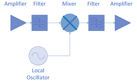
Block Diagram of a Typical LNB
2: How to adjust for phase difference
The PLL works by comparing the phase of the reference sine wave (for most SATCOM systems a 10 MHz reference is used) to the Local Oscillator sine wave. The Reference Signal can be internal to the LNB or external where it would be multiplexed onto the output cable of the LNB and fed from somewhere else. The PLL sets the frequency of a Voltage Controlled Oscillator (VCO), a Coaxial Resonator Oscillator (CRO), or a Dielectric Resonator Oscillator (DRO) to generate the Oscillator frequency. The reference signal is usually at a lower frequency than the oscillator. For the PLL to compare the phase the two frequencies must be the same, so in the case of a Ka Band LNB it must divide the Oscillator (usually a higher frequency than the reference) output to match the reference (see the next section for in-depth discussion about matching references). If there is a phase difference, adjust the control voltage of the Oscillator which adjusts the frequency of the Oscillator.
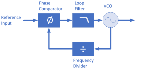
Block Diagram of a Typical PLL Controlled LO
3: A reference is required, not optional
If there is no reference, the PLL will search for phase alignment to a nonexistent reference and could go to either the minimum or the maximum output frequency of the Oscillator or otherwise be unstable. On the spectrum analyzer these low frequency oscillations show like spurs, from which you can tell that the PLL is not locked even if the frequency of oscillator appears correct.
4: How to choose a solid reference
Usually, the reference frequency is from a highly stable quartz crystal. Most LNBs use a 10 MHz reference but higher frequencies of 50 MHz and 100 MHz can give improved performance for some applications. Frequency stability is made up of two main components:
- aging of the crystal
- effects of temperature
Ovenized Crystal Oscillators (OCXO) hold the crystal at a constant, elevated, temperature so aging is typically the only variation of concern. Temperature compensated crystal oscillators (TCXO) use temperature compensating circuits to adjust for the effects of temperature.
With an external reference you can mount your reference oscillator indoors in a controlled environment to negate the effects of temperature.
If you use a reference inside the LNB it is typically a TCXO for two reasons:
1) OCXOs are usually much larger than TCXOs and space is at a premium inside the LNBs, and
2) the heat generated by an OCXO inside would negatively impact the noise figure of the LNB.
Other reference sources can be:
- Rubidium oscillators which are more stable than Quartz crystals but typically have poorer phase noise, and
- GPS Disciplined Oscillators (GPSDO) which are frequency locked to the global GPS satellite networks which are themselves locked to atomic time standards.
The following table shows some typical stability performances:
| TCXO | OCXO | Rubidium | GPSDO | |
| Aging/Day (ppb) | +/-1000 | +/-0.5 | +/-0.005 | +/-0.001 |
| Temp (0 to 40C)(ppb) | +/-1500 | +/-10.0 | +/-0.1 | NA |
Typical reference oscillator performance
5: How to manage reference drift so your LNB doesn’t
The frequency stability of the LNB from Radio Frequency (RF) to Intermediate Frequency (IF) is a function of the reference signal since the PLL locks the LO to the phase of the reference. When the reference drifts by say 1 Hz, the PLL reacts by adjusting the LO Frequency so the phases line up again.
As an example, for an LNB tuned to a WGS Ka-Band satellite (20.2 to 21.2 GHz) the LO is usually 19.2 GHz. To do a phase comparison, the LO signal must be divided down to the same frequency as the reference (10 MHz) which, for this example, need to be divided by 1920. In this case if the 10 MHz reference drifts in frequency by 1 Hz, the PLL will retune the VCO and the result will be the LO frequency moving by 1920 Hz which will result in an apparent move of a carrier on the satellite of 1920 Hz also.
Some LNBs have their PLL and VCO operating at a lower frequency which is then multiplied to the appropriate LO. For example, a 19.2 GHz LO could be generated with a VCO at 3.84 GHz that is then multiplied by 5 (filtered and amplified) to get to 19.2 GHz. In this case the divider is 384, so a 1 Hz change in the reference results in a 384 Hz change in the VCO output. Then the VCO is multiplied by 5 times to get to the LO RF frequency. A frequency multiplier (see this page) takes whatever inputs signal it has and multiplies it, in this case by 5. So, a 1 Hz change going into the multiplier results in a 5 Hz change in the output. Thus a 1 Hz change to the reference will result in 384 x 5 or 1920 Hz change in the LO frequency.
To calculate the frequency stability for our OCXO, in Hz, of the LNB we either take:
- Reference Stability (ppb) * LO Frequency 0.5 x 10⁻⁹ per Day * 19.2 x 10⁹ Hz = ±6 Hz/Day
- Reference Stability (Hz) * (LO Frequency/Reference Frequency)
005 Hz/Day x 1920 = ±9.6 Hz/Day