Specifications
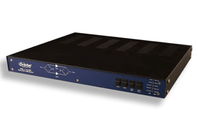
- 2 BDCs in a 1:1 redundancy configuration: Ku External Reference. (C and Ka also available)
- Available in a wide variety of BDC frequency ranges, gains, input and output connectors
- 1 unit high chassis
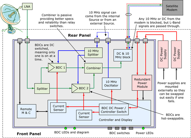
- BDCs are hot-swappable for convenient replacement
- Remote control and monitoring via Ethernet, RS-232, RS-422 or RS-485 connection
- Power supplies are mounted outside of chassis for easy service or replacement.
Functional
- Front panel monitor and control (Remote monitor and control as well)
- Internal 10 MHz source (leave jumper in) or use an external 10 MHz source (take jumper out)
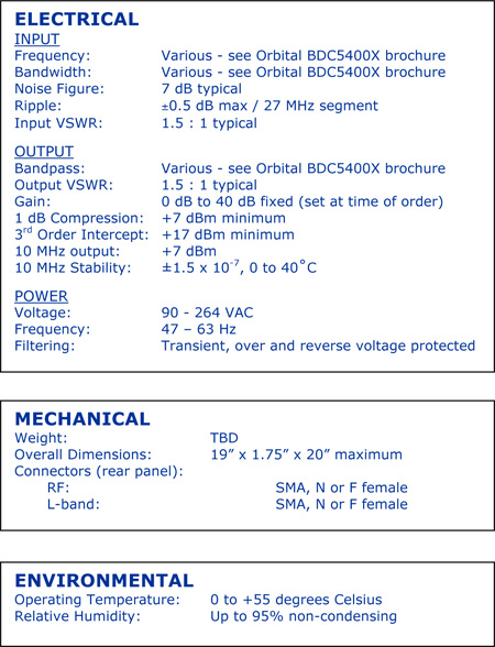
- Global power supplies for use anywhere in the world
Differences over conventional models
- BDCs are switched by using DC to turn each one on or off. Conventional models have both BDCs on at all times. This adds RF & IF noise and transients. It also means that the added heat would affect the overall MTBF and both BDCs will statistically last the same amount of time. If only one BDC is on at a time, there will be less heat generated and the BDCs will last longer. Because they are externally referenced, the BDCs will turn on exactly on frequency.
- Because the BDCs are switched by having only one on at a time, the output switching relay can be a simple combiner. This improves the specs and reliability of the system as a combiner is a passive device and less expensive.
BDC Solutions
The term BDC is commonly used to refer to the modules (which look like an LNB with the waveguide removed and replaced with a connector), and to the rack-mounted unit which might contain from one to several BDC modules. BDCs are increasingly used in outdoor units at the antenna – ODUs, and have an indoor rack mounted controller – IDUs. BDCs are commonly used when a client uses multiple BDCs and a single LNA to cover the entire band.
How to order
For pricing options please call 1-604-419-8585 or contact us.


